
LiDAR Mapping of a Major Arterial Road Intersection for TMR Redesign

Summary
Queensland Drones captured a colourised 3D LiDAR model of a major arterial road intersection and its four approaches, achieving less than 2 cm RMSE over more than one kilometre of road, two intersecting roads and a bushland transmission line corridor.
We were commissioned by a registered surveyor for this project, part of which involved operations within the controlled airspace of Amberley RAAF base. The data helped Queensland Department of Transport and Main Roads (TMR) engineers build a digital twin of the intersection to inform its redesign.
Extensive surveyed ground control tied the model to survey-grade positions and the engineers received a CAD- and BIM-ready package including a classified point cloud, breakline-constrained TIN mesh, DEM, DSM and planimetric features.
The challenge
Redesigning a major intersection needs a complete, survey-grade picture of everything already there, and arterial intersections are among the hardest places to survey on foot due to traffic. Engineers need the exact geometry of each lane, kerb, island, line marking, drain and light pole, plus the levels across the whole junction and well back along each approach.
- Traffic. An arterial intersection carries heavy traffic in every direction. Ground survey crews need traffic control and still spend long periods exposed on live lanes.
- Complex geometry. Curved kerbs, splitter islands, raised medians and changing crossfall mean a ground survey needs a very large number of points to describe the surface properly.
- Four approaches. The model had to extend along all four approach roads, not just the junction itself, so designers could tie the new layout into the existing road.
- Survey-grade precision. The data was going to the state road authority’s engineers for design, so it had to be accurate to a couple of centimetres, not just look right.
Methodology
Queensland Drones set extensive ground control, which was measured and verified by the surveyor, and we filled everything between those points with dense LiDAR data.
- Surveyed ground control. Our team placed and an extensive network of ground control points across the intersection and along each approach, on hard, stable surfaces, which were then measured by the surveyor’s team.
- Flight planning. We planned flights to cover the junction and all four approaches in one consistent dataset. Our planning included liaison with RAAF Amberley to minimise any potential conflict with their air operations, and planning flight lines which minimised operations over the busy arterial road itself.
- LiDAR and RGB capture. We captured LiDAR and imagery together from the air, so the point cloud is colourised and lines up exactly with the orthomosaic. Kerbs, line marking, islands and street lights were all recorded without anyone standing in the traffic lanes.
- In-house processing. Our GIS team processed the all data in-house. The point cloud was manually classified using ASPRS guidelines to separate the road surface and ground from vehicles, vegetation and structures.
- Breaklines and features. Kerb lines, lane edges, island outlines and other grade changes were extracted as breaklines. Fixed assets were mapped as planimetric features including light poles, road signs and other structures.
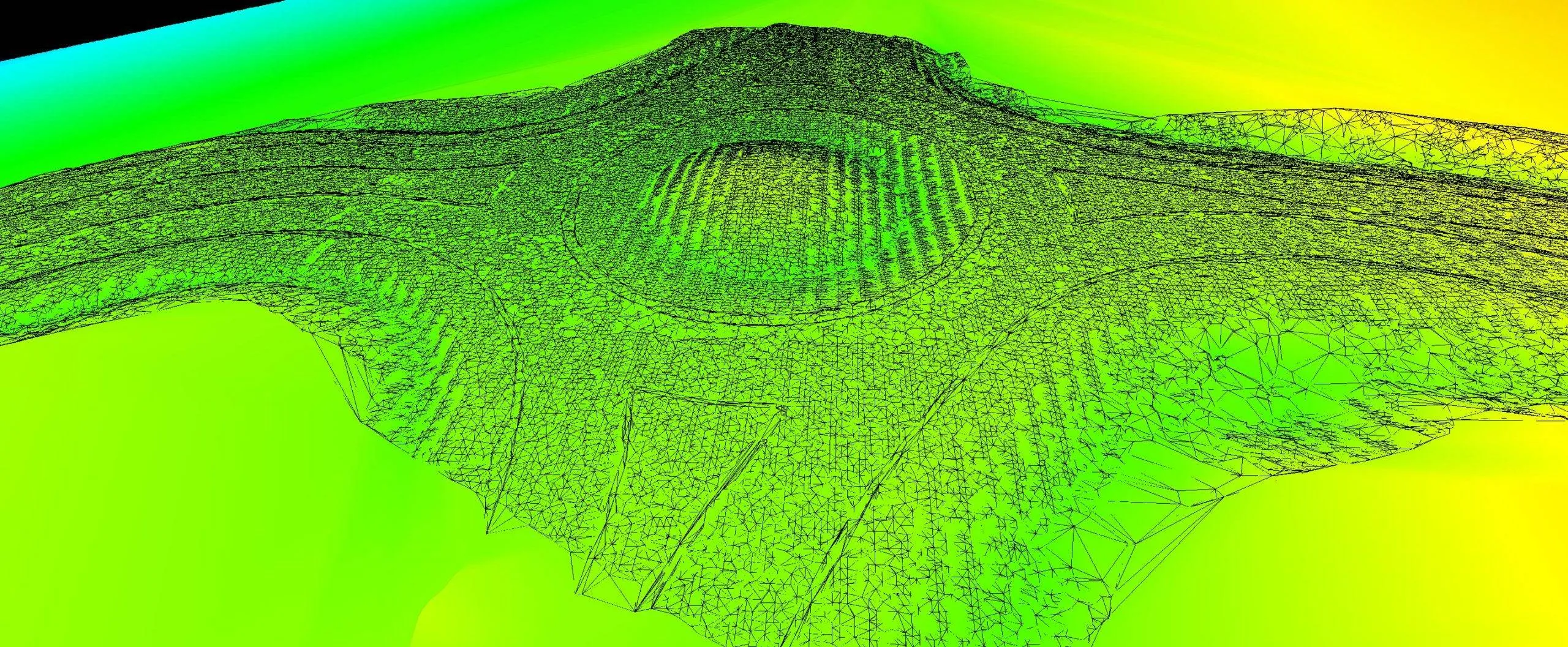
- Surface models. The breaklines constrained a 3D TIN mesh so sharp edges such as kerbs stay sharp in the design surface. A DEM (bare earth) and a DSM (including above-ground features) were produced from the same data.

Deliverables
The surveying company and TMR’s engineers received five CAD- and BIM-ready products, all built from the same validated LiDAR data.
| Deliverable | What engineers use it for |
|---|---|
| Colourised 3D point cloud | The digital twin itself: measure any lane, kerb, island or pole in 3D |
| Breakline-constrained 3D TIN mesh | Existing-surface model for intersection design in civil design software |
| Digital Elevation Model (DEM) | Bare-earth levels for drainage and grading |
| Digital Surface Model (DSM) | Surface including above-ground features, for clearances and sight lines |
| Planimetric feature mapping | Kerbs, lane edges, islands and fixed assets as CAD-ready linework |
Validation
The model achieved less than 2 cm RMSE against the surveyed ground control, over more than one kilometre of road. RMSE (root mean square error) combines every measured difference between the model and the surveyed points into one figure, so it describes the whole model rather than the best single point.
Holding that accuracy across a full kilometre matters. Small errors tend to grow along a long, narrow corridor, and extensive ground control along every approach is what keeps them in check. The hard bitumen and concrete surfaces of an intersection also give LiDAR a clean, well-defined return.
For context, these are the accuracy tiers we normally quote for drone LiDAR. Actual results depend on terrain, ground surface and ground cover.
| Ground control used | Typical horizontal accuracy | Typical vertical accuracy |
|---|---|---|
| None | ~5 cm | ~10 cm |
| Sufficient ground control | ~3 cm | ~5 cm |
| Ground control plus checking by a registered surveyor | ~2 cm | ~3 cm |
| This project | <2 cm RMSE | 2-3cm RMSE |
After completion, the surveyor’s GIS team cross-checked our positional accuracy using spot survey points captured by their own team beyond the ground control and checkpoints established by our team.

Client outcome
TMR’s engineers got a complete, survey-grade digital twin of the intersection and all four approaches to base the redesign on, delivered through the surveying company that commissioned it.
- Less exposure on live lanes: the detail came from the air, so survey crews spent far less time working in busy arterial road traffic. No lane closures were required to complete the survey.
- Complete coverage: the whole junction and its approaches were captured in one dataset, so designers can measure what they need without another site visit.
- Design-ready from day one: breakline-constrained surfaces and planimetric linework load straight into civil design and BIM software.
- Surveyor-backed accuracy: less than 2 cm RMSE over more than a kilometre, tied to the surveying company’s control.
Frequently asked questions
How accurate is drone LiDAR for intersection and road design surveys?
On this project, drone LiDAR tied to extensive surveyed ground control achieved less than 2 cm RMSE over more than one kilometre of road. As a general guide, drone LiDAR achieves around 3 cm horizontal and 5 cm vertical with sufficient ground control, and around 2 cm and 3 cm when control and checks are done by a registered surveyor. In more recent road surveys using our latest enterprise UAVs and LIDAR sensors, we have been able to demonstrate accuracy to 1cm horizontal and 1.5cm vertical.
What is a digital twin of an intersection?
It is an accurate 3D copy of the intersection as it exists today. Here that means a colourised LiDAR point cloud with surface models and feature linework, all tied to survey control. Engineers can measure, cut sections and design against it without returning to site.
Is drone LiDAR used on Department of Transport and Main Roads projects?
Yes. This project supplied colourised 3D LiDAR, through a surveying company, to help Queensland Department of Transport and Main Roads engineers build a digital twin of a major arterial intersection for its redesign.
What is the difference between a DEM and a DSM?
A DEM (Digital Elevation Model) shows the bare ground and road surface, with vehicles, vegetation and structures removed. A DSM (Digital Surface Model) includes everything above the ground, such as poles, signs and trees. Road designers usually need both.
Why does a breakline-constrained TIN matter for road design?
Without breaklines, a surface model smooths over sharp edges like kerbs, lip lines and island edges. Breaklines force the TIN mesh to follow those edges exactly, so the existing surface is correct where the new design has to tie in.
Does drone LiDAR replace a surveyor on road projects?
No. On this project a surveying company commissioned the work and measured the ground control. Drone LiDAR extended their survey across the whole intersection and its approaches in far more detail than a ground survey alone. LIDAR does not replace surveyors, it leverages their skillset over larger areas in a shorter timeframe.
Need an intersection or road corridor surveyed?
Queensland Drones is a CASA-certified drone survey and LiDAR mapping specialist (ReOC #6466). We have operated since 2016 across Queensland, New South Wales and the Northern Territory and we work with surveyors and engineers on intersections, road corridors and other transport infrastructure.
Give Tony a call on 1300 246 977 or request a quote.
Related: Rural Road Corridor Mapping · Urban Streetscape Mapping · Aerial Road and Corridor Mapping · Drone LiDAR for Surveyors and Engineers
